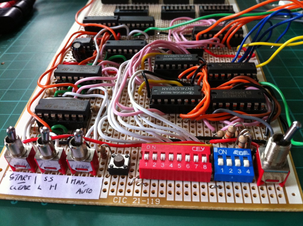
This is my 8-bit computer built from CMOS logic gates, based on the SAP-1 in Albert Paul Malvino’s Digital Computer Electronics. It was hard to avoid creating a rats’ nest of wires, but there is (surprisingly) about 40m of wire in total. Its hard to gauge the amount of detail to describe this project in; there’s enough for a whole book’s worth describing it from the logic gates up, so I’ve provided a brief overview and a video that shows how it works in action!
The computer is fully programmable and it can add and subtract numbers from 0 to 255. The computer is organised around an 8-bit parallel data bus. At its heart is the adder/subtracter, which performs the computer’s calculations, either side is a register, which together hold the two numbers to be added or subtracted. Once the calculation has taken place, the result is stored in the upper register, which is called the accumulator. The result can then be sent to the output register, which drives the 8-bit LED display, or further operations can take place.
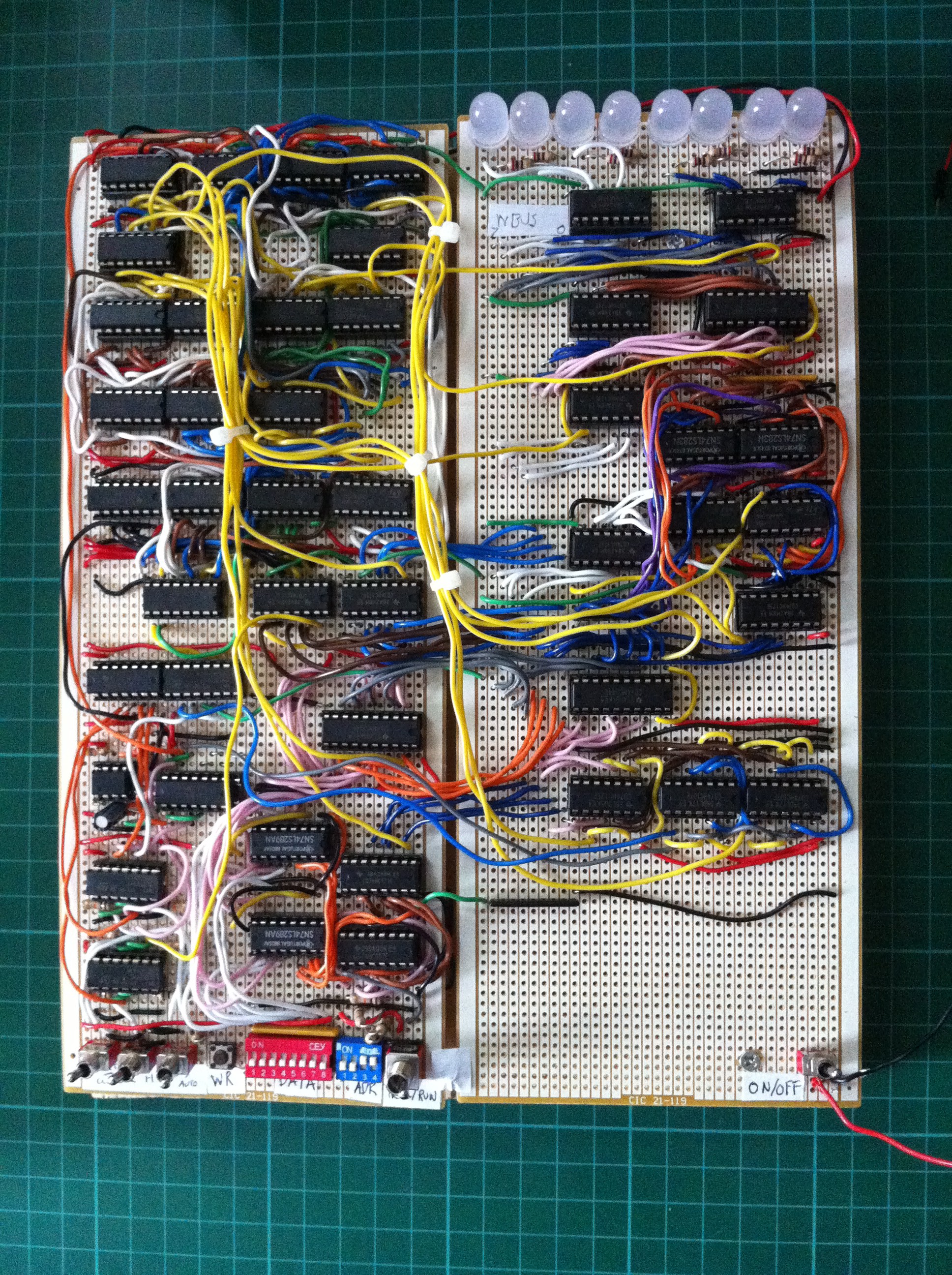
Data and instructions are stored in the RAM, which is the most complex chip on the computer. Two chips of 16 4-bit words each combine to make one 8-bit word; giving the computer a total memory of 16 bytes.
A 555 timer divided by a flip-flop provides the clock and drives two counters. First, the program counter, which is used for loading instructions, and second the ring counter, which generates T states for the control logic, which is made entirely of NAND gates and inverters.
The two most complex chips are the RAM and the 4-bit adder, all of the other components are Logic Gates or Flip-flops. Incidentally, these are the only TTL chips on the computer as they were not available as CMOS. Their inclusion has taught me the practicalities of level shifting.
Whilst the computer’s functions are basic, building it has taught me the fundamentals of digital logic and computer architecture. Also, reading how these work in a book is very different from making them a practical reality.
Programming
The computer has 5 instructions:
LDA 0000 +4 bit address which loads a number into the accumulator, this must be the first command.
ADD 0001+4 bit address adds a number at a 4-bit address to the accumulator.
SUB 0010+4 bit address subtracts adds a number at a 4-bit address to the accumulator.
OUT 1110 XXXX outputs the accumulator value to the display
HLT 1111 XXXX stops the computer’s clock. All programs must end with this instruction.
These instructions are loaded into the upper nibble (4-bits) of the computers memory and where an address is needed it is added to the lower nibble. The program counter starts at 0000 and continues counting upwards to 1111 unless a HLT instruction is received, so numbers to be added or subtracted have to be entered in memory locations after the HLT. This is shown in my video, where I write a program to do the sum 63 + 111 – 56 = ?
The program is as follows:
ADDRESS + DATA
0000 00000101 @Load Value at address 5 into the accumulator
0001 00010110 @Add Value at address 6 to the accumulator
0010 00100111 @Subtract Value at address 7 from the accumulator
0011 1110XXXX @Output result to LED display
0100 1111XXXX @Stop the computer
0101 00111111 @63 in binary
0110 01101111 @111 in binary
0111 00111000 @56 in binary
Output = 01110110 in binary or 118